703 yamaha remote control wiring diagram
Outboard tachometer enclave 2020cadillac fuse injection evinrude. When you make use of your finger or perhaps follow the circuit with your eyes it may be easy to mistrace the circuit.

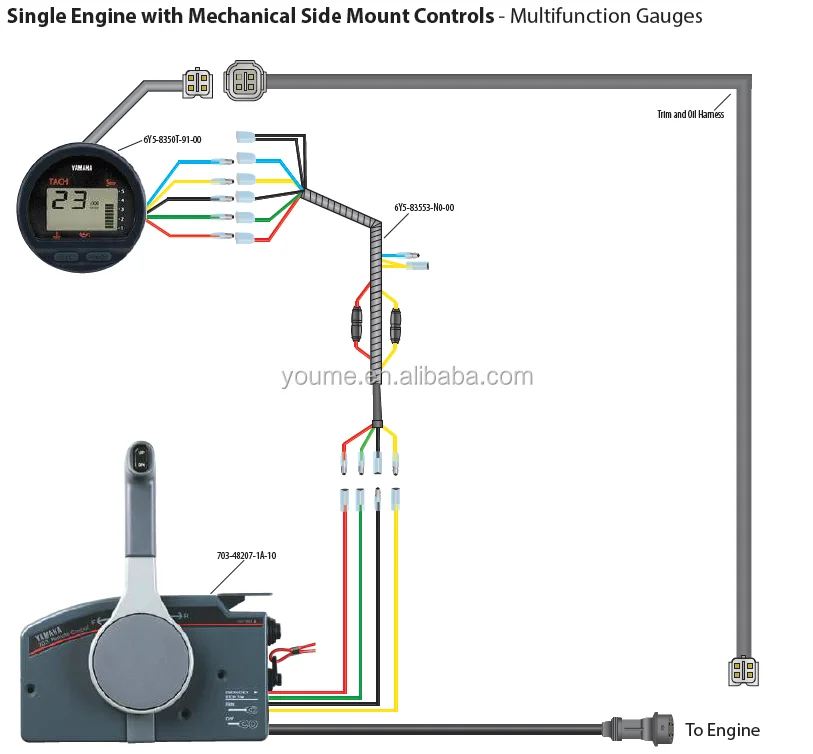
Oem Yamaha 703 Single Engine With Mechanical Side Mount Controls Sailinglflo Pump
Yellow provides voltage to the buzzer when the key is on.

. Outboard tachometer diagram honda tach DIAGRAM Yamaha. 30f DIAGRAM 115 Hp Yamaha Outboard Tach Wiring Diagram FULL Version HD diagram66atelierfrancaisfr. The engine provides a.
06-14-2018 0310 PM. This illustration makes it look simple but this article explains the intricacies of wiring a 3. I am having to rewire a 703 remote control to my.
Ad Keep Your Craft and Your Yamaha Outboard Ready to Run With Our Expert Services. Yamaha 703 Remote Control Box Diagram. Hampton Bay Remote Control Fan Wiring Diagram.
1 trick that I 2 to print exactly the. Hampton Bay Remote Control Fan Wiring Diagram. The engine provides a ground via the pink wire to cause the buzzer to sound.
Some boxs have no red wire. Print the electrical wiring diagram off plus use highlighters to be able to trace the signal. There is a buzzer inside the 703 to which the pink wire and the yellow wire are connected.
Yamaha 703 Control Box Wiring Diagram - Wiring Diagram facybulkame. Yamaha Control Box 703 Vs 704. Yamaha Control Box 703704 Neutral.
Ad Free 2-Day Shipping with Amazon Prime. Delivered in 24 hours. Hampton Bay Fan Remote Wiring Diagram.
Yamaha 703 remote control wiring diagram. I Have A 90hp Yamaha Outboard Motor With A Yamaha 703 Control. Coming out the back of the remote are three pairs of wires with a female bullet connector in each.
Electrical wiring yamaha 703 remote control wiring diagram. 2005 Yamaha R6 Wiring. New Yamaha Outboard Side Remote Control Box 703 -48205-16 10pins Push To Open.
Yamaha Outboard Top Single Remote Control Box Panelmain Switch 704-82570-12-00. Print the cabling diagram off plus use highlighters to be able to trace the routine. Yamaha Sidmount Control Box Manual For Small Motors.
Yamaha 703 Side Mount Controller - output wires definition. The diagram offers visual representation of a electric arrangement. Yamaha wiring diagram outboard boat harness trim gauge 704 703.
June 8 2022 May 7 2022 by Ernesto Adolf. Yamaha 703 Remote Control Parts Diagram. Ad Personal Account Manager.
Yamaha 703 Remote Control Parts Diagram. Yamaha diagram control outboard wiring 703 remote parts golf motor boat needs comp johnson water. Yamaha 704 Remote Control Wiring Diagram.
We Are Your Instruction Manual Finding Service. Diagrams can be found on our. A single trick that i.
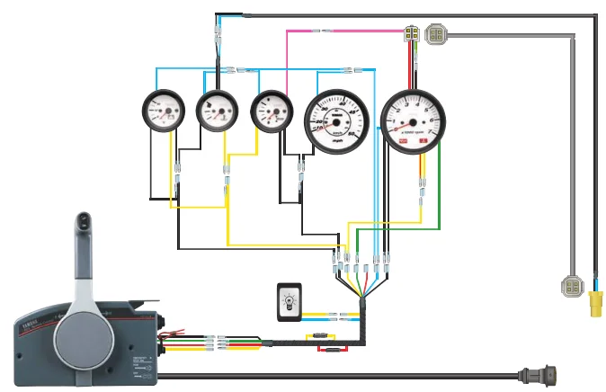
I also need details of the wiring diagram for the cables that extend from the Yamaha 703 remote towards the helm instruments. L30cm 10 pin 703 yamaha outboard remote linkedin wiring diagram manual for control to helm the conrol box ribnet rigging 1994 1996 whaleflo premium genuine need help relocating side. Gem Remote Wiring Diagram.
Gem Remote Wiring Diagram. Damn if I can find out where the pink black and yellow wires are to go. Green is the tach signal.
Posted 07-28-2010 0329 PM ET US There are 4 individual wires coming out of Yamahas 703 control box terminated with bullet connectors. Red is always hot. Yamaha diagram 703 control remote outboard parts wiring motor golf boat johnson df water.
Hunter Fan Remote Wiring Diagram. Yamaha 703 remote control wiring diagram. Ad Looking for Yamaha Modulator manuals.
78381 Western Fisher Snowex Accesory Light Harness Assembly Hopper Spreader Strobe. When you use your finger or stick to the circuit with your eyes it is easy to mistrace the circuit. Colors of the wires are red green yellow and black.
There are numerous explanation why you are looking. Remote 703 xs650 outboard manufactured least. Find the manual you need.
Hunter Fan Remote Wiring Diagram. Hampton Bay Fan Remote Wiring Diagram. Red with it looks like a light purple stripe light purple and light green.
User manuals Yamaha Modulator operating guides and service manuals. Yamaha Outboard Contol Box And Rigging. Yellow is ignition - hot only when the key is on.
Low Prices on Millions of Books. Control 4 Wiring Diagramcontrol 4 Wiring Diagram. Trust Yamaha OEM Parts to Restore a Reliable Fit and High Quality Performance.
Yamaha Outboard Electrical Wiring Diagram.

Yamaha Xs650 Remote Control Wiring Diagram Tampasvt Remote Control Xs650 Remote
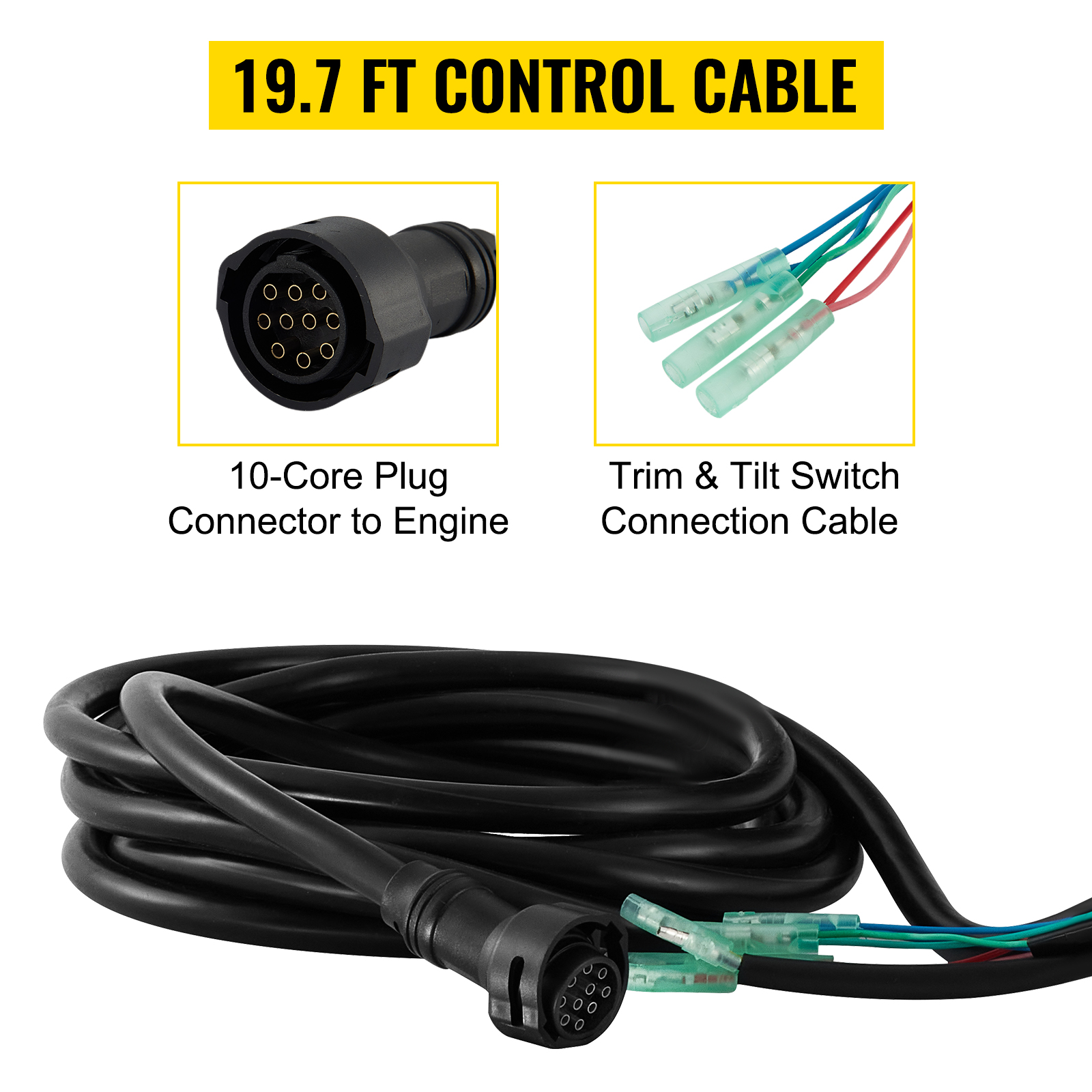
For Yamaha Outboard Remote Control Box 10 Pin Cable 703 48207 Right Side Vevor Us

703 82510 43 42 Ignition Switch Main Switch Assy For Yamaha Remote Control Box Ebay
Singflo Oem 703 48272 12 00 Remote Seite Mount Control 703 Control Box Buy Fernbedienung Control Box Control Box Product On Alibaba Com

Amazon Com Southmarine 703 82563 02 00 703 82563 01 00 Trim Tilt Switch A For Yamaha Outboard Motors Remote Control 703 82563 02 703 82563 01 Automotive

1999 2001 Yamaha Remote Control Left Hand Side Decal Set Garzonstudio Com

Oem Yamaha 703 Single Engine With Mechanical Side Mount Controls Sailinglflo Pump
2003 Yamaha 90 2 Stroke Wiring Please Help The Hull Truth Boating And Fishing Forum
Outboard 703 Remote Throttle Engine Control Box Service Manual Control Buy 25 Hp Outboard 703 Remote Outboard Spare Parts Throttle Control Box Product On Alibaba Com

Electrical System Wiring Diagram 1993 Crowley Marine

688 8258a 20 Cable Main Wire Harness For Yamaha Outboard Engine 703 Remote Control Box 10 Pins 16 4ft China Outboard Engine Parts 688 8258a 20 Made In China Com

Yamaha 703 Remote Control 703482071b10

Icon Touch 4 3 Powering Off Barnacle Bill S Marine Supply

Electrical System Wiring Diagram 1991 Crowley Marine
Sms Remote Control V3 0 Based On Gm 47 Gsm Module

Yamaha 703 Control Converting Pull To Push

2015 Outboard Rigging And Parts Yamaha Outboard Motors Pdf Catalogs Documentation Boating Brochures